Youtube

Youtube
GYAN & VIGYAN

Tuesday, July 23, 2024

FluidFlow


Fan Laws and Fan Performance

This blog gives a general outline of the rules or laws which can be used to predict fan performance in a given system. Why are the fan laws important? As an example, let’s consider the fan curve typically provided by a manufacturer. This fan curve is usually measured at “standard” or other stated conditions. In real systems, it is unlikely that a fan will be spending its operating life at these identical conditions. Furthermore, suction pressure variations, density changes, composition changes, etc are common and can also affect how the fan will operate in the system.

The fan laws help us estimate how a fan will operate in a system at different speeds, fluid density, impeller diameter, etc. Once we have a basic understanding of these laws, the performance of a fan can be calculated for various conditions.

The performance of geometrically similar fans of different sizes or speeds can be predicted with reasonable accuracy for practical purposes using the fan laws. A higher level of accuracy would require the effects of say, the viscosity of the gas, surface roughness of the fan, scale effect also be considered. However, depending on the level of accuracy required, for many fan calculations, this may not be necessary.

One point to note is that the laws apply to the same point of operation on the fan curve. They cannot be used to predict other points on the fan’s curve. The fundamental fan laws governing fan performance are generally only valid for a fixed system with no changes in airflow characteristics in the system or changes in aerodynamics. The term “system” refers to the combination of ducting, filters, grilles, dampers louvres, hoods, etc through which air is distributed.


As we know, the movement of air through a system causes friction/resistance between the air molecules and their surroundings and any other air molecules. Energy is therefore required to overcome this resistance. The faster the air moves through the system the greater the resistance imposed to flow and the more energy required to deliver the air through the system. This energy is described in terms of pressure. In general, the pressure required to overcome the resistance is referred to as static pressure. The pressure that results in the air/gas velocity is described as velocity pressure and the combination of these two values is often referred to as total pressure.

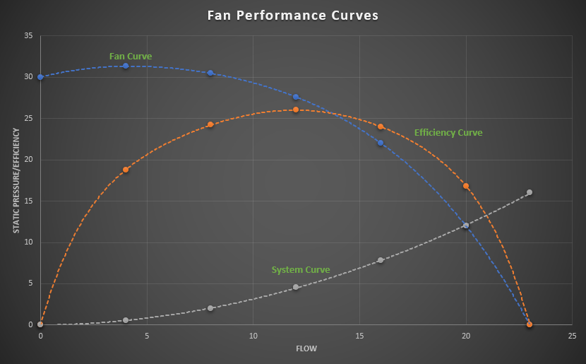
Fans or blowers are often installed in the ventilation or industrial process systems to overcome the resistance. Fan performance is often represented in the form of fan curves. The curves are based on a specific set of conditions which typically include speed, volume, efficiency, static pressure and power required to drive the fan at the given set of conditions. Figure 1 provides a typical illustration of fan curves. The point where the static pressure curve intersects the system resistance curve represents the duty-point for the fan.
Fan Performance Curve
Figure 1: Manufacturer’s Fan Performance Curve.

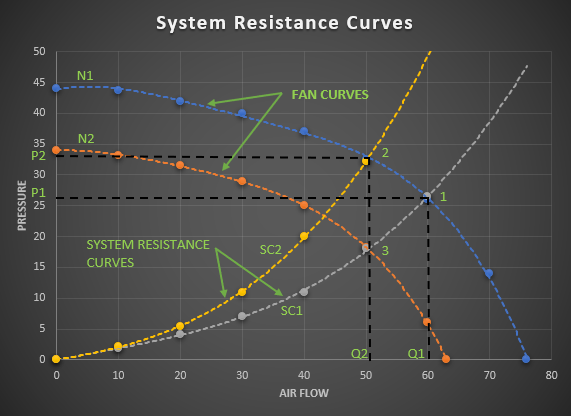
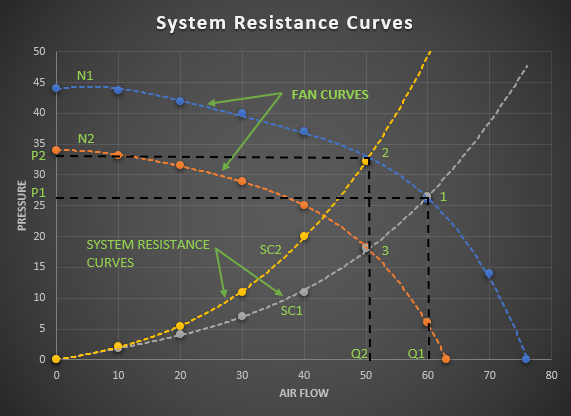
As noted earlier, as the airflow is increased in any fan system, the system resistance also increases. In a fixed system, it is said that the pressure required/system resistance varies with the square of the volume of air flowing through the system. The system resistance curve can be developed by determining the pressure required over a range of system flow rates. This resistance curve can then be plotted on the fan performance curve (also known as the fan capacity curve) to identify the actual duty-point. This is shown as point “1” in Figure 2 where the fan curve N1 and system resistance curve SC1 intersect. This duty-point is at airflow Q1 which is delivered against pressure P1.
System Resistance Curves
Figure 2: System Resistance Curves.

Fans operate along a performance curve as provided by a manufacturer for a given fan speed. If we wish to reduce the air flow in the system, we could for instance partially close off a damper in the system or reduce the fan speed. Partially closing a damper will result in a new system resistance curve. This is shown as system resistance curve SC2 where the required pressure increases for any given air flow. The fan will now operate at duty-point 2 to provide the reduced air flow Q2 against the higher pressure P2.

On the other hand, we can reduce the fan speed from say N1 to N2 to reduce the airflow in the system and keep the damper in the fully open position. Under these conditions, the fan will now operate at duty-point 3 to provide the same airflow rate Q2 but at a lower pressure.

Therefore, reducing the fan speed is a much more energy-efficient approach to reduce airflow since less power will be required resulting in less energy consumption.

Fan Laws

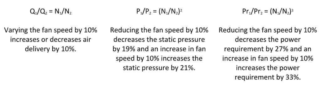
In general, the fan laws are typically used to calculate changes in flow rate, pressure and power of a fan when the size, speed or gas density is changed. In the fan laws outlined in Table 1 below, the subscript 1 represents the initial existing condition and subscript 2 represents the desired calculated condition.
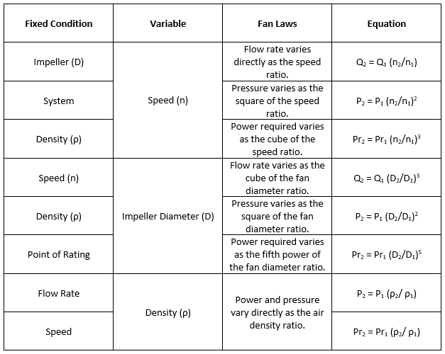

The illustration in Figure 3 helps illustrate the effects of changes in fan speed.
Pressure & Power due to changes in fan speed
Figure 3: Effects on Flow, Pressure & Power due to changes in fan speed.

The fan laws are a group of equations used to determine the effects of changes in the fan operating speed, the fan diameter or the density of the air in the system. The performance of a centrifugal fan, axial fan or blower is often given as a series of pressure, efficiency and shaft power characteristic curves plotted against air flow rate for specified values of speed, air density, and fan dimensions. It is, therefore, useful to determine the operating characteristic of the fan at other speeds and air densities. Using the fan law relationships, families of fan curves can be developed for operating the fan at different speeds, etc.

The fan laws can also be utilized to consider test results obtained from smaller prototype fans to predict the performance of larger fans which are of course geometrically similar.

Knowing the performance of a given fan under set specified operating conditions, variations in the performance can be predicted according to the fan laws. It should be noted however that adding or removing components of a fixed system such as dampers or incurring density changes will create an entirely different system resistance curve. Also, it’s worth noting that changing fan accessories such as inlet dampers, inlet boxes will change the fan performance curve from the standard. This should, therefore, be considered before considering or applying the fan laws.

As part of the system design, the fan laws can be quite useful in determining alternate performance criteria or in establishing a minimum and maximum range. In the event that “safety factors” have been applied to system design calculations, it is worth noting that, based on the fan laws, a 10% increase in volume will result in a 33% increase in power requirement. Due consideration is therefore recommended on evaluating any applied “safety factors” against the actual cost penalty incurred.

In general, using these rules or fan laws, once we know the performance of a given fan under set specified operating conditions, variations in the performance can be predicted with reasonable levels of accuracy. FluidFlow software considers the effects of compressibility, suction pressure variation, etc whilst also solving the fan laws ensuring a high level of accuracy.

Wednesday, November 8, 2023

Circuit Breakers- Discrimination /Selectivity and Its Techniques

 A circuit breaker is a switching device which can be operated manually and automatically for control and protection of electrical power circuit.

The primary purpose of a circuit breaker is to protect the system from the damage in series connected equipment & to minimize the area of damage and to minimum duration of power loss. However the first consideration in the discrimination is the correct circuit sizing breaker of main and branch breaker.
Discrimination is the coordination between the operating characteristics of circuit breakers placed in series. When the fault occurs in system only the circuit breaker placed immediately upstream of the fault will trip.

Discrimination as per IEC 60947-2 can be defined as follows:

  1. The total discrimination: This is a type of current based discrimination where in there are two circuit breakers in series, the circuit breaker on the load side effects the protection without causing the upstream circuit breaker to operate/trip
  2. Partial Discrimination: This is a type of current based discrimination where in there are two circuit breakers in series, the circuit breaker on the load side effects the protection up to a defined level of overcurrent, without causing the upstream circuit breaker to operate/trip.
Principles of discriminative tripping (selectivity)

Discrimination may be total or partial, and based on the principles of current levels, or time-delays, or a combination of both. A more recent development is based on the logic techniques Discrimination is achieved by automatic protective devices if a fault condition, occurring at any point in the installation, is cleared by the protective device located immediately Upstream of the fault, while all other protective devices remain unaffected.

  • Protection against overload: discrimination based on current levels
    This method is realized by setting successive tripping thresholds at stepped levels, from downstream relays (lower settings) towards the source (higher settings). Discrimination is total or partial, depending on particular conditions, as noted above.
  • Protection against low level short-circuit currents: discrimination based on stepped time delays
    This method is implemented by adjusting the time-delayed tripping units, such that downstream circuit breakers have the shortest operating times, with progressively longer delays towards the source.
Current-level discrimination – Principle

Current-level discrimination is achieved with stepped current-level settings of the instantaneous magnetic-trip elements. Current-level discrimination is achieved with circuit breakers, preferably current limiting, and stepped current-level settings of the instantaneous magnetic-trip elements.
The downstream circuit-breaker is not a current-limiter device
Total discrimination in this situation is practically impossible because
Isc A ≈ Isc B, so that both circuit-breakers will generally trip simultaneously. In this case discrimination is partial, and limited to the Im of the upstream circuit-breaker.
The downstream circuit-breaker is a current-limiting device. Improvement in discriminative tripping can be obtained by using a current limiter for circuit-breaker B. For a short-circuit downstream of B, the limited level of peak current IB would operate the (suitably adjusted) magnetic trip unit of B, but would be insufficient to cause circuit-breaker A to trip.

Time-based discrimination- Principle

This technique requires:
The introduction of time-delays into the tripping mechanisms of circuit breakers
Circuit Breakers with adequate thermal and mechanical withstand capabilities at the high current levels and time delays considered Two circuit-breakers A and B in series (i.e. carrying the same current) are discriminative if the current-breaking period of downstream circuit-breaker B is less than the non-tripping time of circuit-breaker A
C&S offers total discrimination up to fault level of 50kA. For total discrimination, the customers can select Winmaster2 Air Circuit Breakers (ACBs) & Winbreak2 Molded Case Circuit Breakers (MCCBs). Customers can refer selection of up- stream and down-steam breaker details (kA, Rating & AF) from the selection tables provided by C&S Electric.

RCCB – Residual Current Circuit Breaker


Table of Content

1. Principle behind RCCB.
2. Benefits Of RCCB.
3. Sensitivity Of RCCB.
4. Limitations Of RCCB.
5. Classification Of RCCB.

While electricity has become an indispensable component of our lives, the fact is, it comes with its own hazards to human life and property. Electrocution and fire being the two major risks associated with electricity, one cannot afford to be negligent when it comes to insulating equipment.
Residual Current Circuit Breaker (RCCB) is an important safety measure when it comes to protection of electrical circuits. It is a current sensing device, which can automatically measure and disconnect the circuit whenever a fault occurs in the connected circuit or the current exceeds the rated sensitivity.

Aimed at protecting an individual from the risk of electric shocks as well as electrocution and fires, RCCB is particularly helpful in instances of sudden earth fault. The presence of RCCB ensures that in such cases, the circuit will trip immediately and the person is thus protected from an electric shock.

Principle behind RCCB

RCCB works on the principle of Kirchhoff’s law, which states that the incoming current must be equal to the outgoing current in a circuit. RCCB thus compares the difference in current values between live and neutral wires. Ideally, the current flowing to the circuit from the live wire should be the same as that flowing through the neutral wire. In case of a fault, the current from the neutral wire is reduced, the differential between the two known as Residual Current. On spotting a Residual Current, the RCCB is triggered to trip off the circuit.

A test circuit included with the Residual Current device ensures that the reliability of RCCB is tested. When the test button is pushed, the current starts to flow through the test circuit. As it creates an imbalance on the neutral coil of the device, the RCCB trips and supply is disconnected thereby checking RCCB’s reliability.

Benefits of RCCB

  • Provides protection against earth fault as well as any leakage current
  • Automatically disconnects the circuit when the rated sensitivity is exceeded
  • Offers possibility of dual termination both for cable and busbar connections
  • Offers protection against voltage fluctuation as it includes a filtering device that guards against transient voltage levels.


Sensitivity of RCCB

A human being is able to sustain an electric shock to the extent of 30 mA. While upto 10 mA may just evoke a prickling sensation, 10 mA onwards may lead to muscular contraction, further leading to a respiratory paralysis at around 30mA. RCCBs are therefore designed to look for small changes in residual current. In cases where protection from fire is sought, RCCBs are also used to track higher changes in residual current of up to 300mA.

Limitations of RCCB

While RCCB has many advantages, it has some limitations as well:

  • RCCB does not guarantee to operate if none standard waveforms are generated by loads. It’s mainly because RCCB is designed to operate on normal supply waveforms.
  • There might be some unwanted tripping of RCCB. It’s mainly because whenever there are sudden changes in electrical load, there can be small current flow to earth especially in the old appliances.
  • RCCB does not protect from current overload. It has been designed to protect only when the live current and neutral current are different. However, a current overload cannot be detected.
  • RCCB does not protect against line-neutral shocks. It’s mainly because current in them is balanced. The current gets balanced as both terminals are held together.
  • RCCB does not protect from the overheating that strike if conductors are not properly screwed into terminals.


Classification of RCCB

RCCB are of two types; the 2 Pole RCCB and 4 Pole RCCB.

2 Pole RCCB:

This is used in case of a single-phase supply connection that has only a live and a neutral wire.

4 Pole RCCB:

This is used in case of a three-phase supply connection.

Rating from 10 Amp ….100 Amp
Sensitivity 30,100,300 m Amp

RCCB is therefore extremely important in providing real time protection for circuits. In industries and high voltage commercial set ups especially, its importance cannot be undermined as there is always risk of shocks and accidental deaths on account of it. At C&S Electric, we offer Wintrip RCCB, a state-of-the-art product fit for industrial, residential and commercial application. C&S RCCBs conforms to IEC 61008 – 1 and is used for both control and isolation of electrical circuits. Being a respected global brand for power management products for over 50 years, with C&S Electric you can rest assured knowing that you are in safe hands.


MCCB: Uses, Applications & Advantages


Table of Content

1. Specifications of MCCBs
2. Components of Molded Case Circuit Breakers
3. There are several advantages of the MCCB
4. Thermal Overload
5. Short-circuit Condition
6. Ground Fault condition
7. Wrong Selection of MCCB

MCCB is the device which is manufactured as an integral inner supporting and enclosed housing of insulating material. It is required for making, carrying and breaking currents between separate contacts under normal circuit condition and abnormal circuit condition such as those of overload condition and short circuit condition. MCCBs provide protection to low-voltage distribution system.

Quenching the arc in air inside the moulded case, the MCCBs interrupt current with range from few amperes to several kilo-amperes. MCCBs are useful for protecting the system against faults like Overload & Short Circuit, with the help of release which may be Thermal Magnetic or Microprocessor Type. MCCB satisfies the requirement of isolation as it provides complete isolation to the circuit.. Compact Size, Lower Downtime, Reduction in inventory & Availability of various accessories makes it a distinctive product.

Specifications of MCCBs:

  1. Ue – Rated Operational Voltage
  2. Ui – Rated Insulation Voltage
  3. Uimp – Impulse withstand voltage
  4. In – Nominal Rated Current
  5. Ics – Service Short Circuit Breaking Capacity
  6. Icu – Ultimate Short Circuit Breaking Capacity


Components of Molded Case Circuit Breakers

Operating Mechanism:

The Operating Mechanism handles the opening and shutting of the contacts. The speed that the contacts open or close is free of how quick the handle is moved. The breaker can’t be kept from stumbling by holding the handle in the on position. The handling will be in a halfway position when the contacts are stumbled.

Arc Extinguisher:

An arc is made at whatever point an electrical switch interferes with a present stream. The Arc Extinguisher’s activity is to limit and separation that circular segment, subsequently stifling it. At the point when an intrusion happens and the contacts partitioned, the present course through the ionized area of the contacts actuates an attractive field around the bend and the circular segment douser.

Trip Unit:

The Trip Unit is the cerebrum of the electrical switch. The capacity of the unit is to trip the working system in case of an abnormal condition. Electronic trip units are presently accessible and they can give considerably more refined insurance and observe.

The MCCB Working in itself is an incredible invention. The MCCB is a choice to a wire since it needn’t bother with a substitute once an over-burden is taken note. Dissimilar to a wire, this electrical switch can be just reset after a misstep and offers improved administrator security and straightforwardness without procuring working expense. For the most part, these circuits have warm current for overcurrent and the attractive component for impeding to work quicker.

 There are several advantages of the MCCB:  

  • MCCBs are Compact in the measure. Hence it spares a significant space inboard plan.
  • MCCBs has to limit downtime. Dissimilar to in a breaker-based framework, there’s no looking for a substitution intertwine. It very well may be Reset and Switched On again instantly in the wake of finding the blame that caused the stumbling amid activity.
  • MCCBs can clear a few blame previously it is expected for substitution.
  • MCCBs are “Upkeep Free” and its repeating costs are less.
  • At the point when MCCBs are utilized, at that point, there is no probability of single staging because of blame in just a single stage.
  • Some multi-reason adornments can be fitted with the MCCB.

MCCB with the combination of one or the two different trip elements will protect the circuit against situations such as: 

Thermal Overload:

In the conditions of overload, there is a temperature between the insulation and conductor. If the insulation remains unchecked, its life will reduce and the maintenance would be higher. It is important to catch the approach of MCCB for the better flow of circuit and lifelong approach of the product.

Short-circuit Condition:

It is the conditiondue to an intentional or unintentional low impedence path creation between phase wires or a neutral & phase wires, this situation leads to an excessively high current flowing through the circuit & voltage becomes negligible

Ground Fault condition:

It is also the type of the short circuit which is linked with the ground phase. This is the common fault which takes place in the low voltage.

The MCCB protects the huge amount of mess and protects the system while enhancing the capability. The MCCB is highly durable and the life of these gadgets are longer than usual gadgets. It is suitable for the higher energy impact. The gadget must be installed by the professional because it is not that easy to be installed and once it is done, you are free to form the obstacles that you might face regarding electricity, short-circuits, and the low-voltage.

Now days MCCBs are available with 2 kinds of release, one is with thermal-magnetic &other is microprocessor release.

Thermal-magnetic uses the principle of bimetal and electro-magnetic coil. Thermal protection is required for O/L & electromagnetic or solenoid is used for S/C. but since electromagnet is a peak sensing device thus a slight transient peak can cause nuisance tripping of MCCB. This CB gives following protections

  • Thermal /Overload Protection- Through Bimetal
  • Electromagnetic /Short Circuit Protection- Through Electromagnet
  • Under Voltage Protection- Through U/V Release

Microprocessor or electronic release sense true R.M.S value of current. It is simulated and calculated from peak values, which are detectable by microprocessor. The microprocessor based release may offer below protections which can be add on:

  • Earth Fault
  • Neutral protection
  • Instantaneous Over-ride
  • Earth Leakage
  • Current Unbalance
  • Overvoltage


Wrong Selection of MCCB:

For few special applications, manufacturers recommend to use MCCBs dedicated to that application. For Ex. For motor back up protection there is a requirement for overload protection of motor, it is required to match the overload settings of MCCB with that of motor. This solution assures no damage to the motor in case of motor overloading. However life expectancy of contactor as per the circuit design is considered better than that of MCCB. Hence this combination will give much lesser life, thus it can’t be suggested. Also we can’t have the single phasing protection by using MCCB. Hence, in this case ‘Type 2’ coordination charts shall be referred so as to make an appropriate selection.

Everything You Need to Know About Circuit Breakers: Introduction, Applications, and Types


Table of Content

1. What is CIRCUIT BREAKER
2. NEED OF CIRCUIT BREAKER
3. TYPES OF CIRCUIT BREAKERS
4. CIRCUIT BREAKERS AT A GLANCE
5. MEDIUM VOLTAGE & HIGH VOLTAGE CIRCUIT BREAKERS


What is CIRCUIT BREAKER

The circuit breaker is a switching device which also offers protection by tripping & cutting off the supply to load in case of fault. Primarily the circuit breakers are used for switching of different kinds of load in Industries, Buildings, Commercial Complexes, and Hotels, etc.

NEED OF CIRCUIT BREAKER

Many kind of abnormal conditions are there which exist in our electrical system that have the potential to damage the circuit & its components. These conditions are defined as ‘FAULTS’.Further, fault is categorized as mentioned below:

  • Overload
  • Short Circuit
  • Earth

In order to keep our electrical components & system safe, it is mandatory to protect our system against the above faults. This leads to the need of circuit breaker.


TYPES OF CIRCUIT BREAKERS

Circuit breakers mainly are categorized on the basis of application as per voltage:

1) Low Voltage Circuit Breaker

2)  Medium Voltage Circuit Breakers

3) SF6/VACUUM Circuit Breakers

4) High Voltage Circuit Breakers

  • VCB
  • SF6
  • OCB
  • ABCB


CIRCUIT BREAKERS AT A GLANCE:

LOW VOLTAGE CIRCUIT BREAKERS

Circuit Breakers operating for the voltage up to 1KV are LV or Low Voltage Circuit Breakers which are as follows:

  • MOLDED CASE CIRCUIT BREAKER (MCCB)

MCCB or Molded Case Circuit Breaker is a kind of circuit breaker which is enclosed in the moulding or housing of a moulded material & that is the reason it is known as Molded Case Circuit Breaker. It is generally used for the current ratings upto 1600A & fault level upto 150KA. It offers protection against overload & short circuits through bimetal & solenoid, these days Microprocessor based MCCBs are being very popular due to the quick functioning of their electronic type release.

  • MINIATURE CIRCUIT BREAKER (MCB)

MCB or Miniature Circuit Breaker is a circuit breaker which is used for protection where current ratings are lower. It can be used upto 125A circuits & like MCCBs it also offers protection against overload & short circuit through bimetal & solenoid. These days Class 3 MCBs are very popular due to their ability of tripping quickly & also minimum loss of let through energy.

  •  AIR CIRCUIT BREAKER (ACB)

AIR CIRCUIT BREAKER or ACB as the name suggests it’s the circuit breaker where the medium of arc quenching is air. ACB is used for the high current applications, or we can say that ACB can offer protection against overload & short circuit upto 6300A. Tripping in ACB is achieved through release. The release is known as the mind of ACB as it only suggests the ACB to trip in case of fault.

  • MOTOR PROTECTION CIRCUIT BREAKER (MPCB)

MPCBs are used specially for motor protections. MPCB as a standalone device offers protection against Overload, Short Circuit & Single Phasing, thus is used specifically for motor applications.

  • RESIDUAL CURRENT CIRCUIT BREAKER (RCCB)

RCCBs as the name suggests offer protection against Earth Leakage. It is used in homes, offices & industries according to the current sensitivity required as per application. In case of current leakage it senses the same & trips thus, saving the human & circuit from shock & adverse effects of current leakage.


MEDIUM VOLTAGE & HIGH VOLTAGE CIRCUIT BREAKERS

Voltage level from 1KV-69KV is categorized under medium & 69KV-230KV is categorized as High Voltage. Circuit Breakers operating in these voltage ranges are known as Medium & High Voltage CBs respectively.

  • VACUUM CIRCUIT BREAKER  (VCB)

Vacuum Circuit Breaker or VCB is used for Medium Voltage applications. In VCB the contacts operation & arc quenching takes place inside bottles where Vacuum is present.

  • SF6 CIRCUIT BREAKER

SF6 circuit breakers are also used mainly in medium voltage applications. In this breaker SF6 gas is used for arc quenching due to its ability of quenching the arc very efficiently. SF6 Breakers being highly efficient in arc quenching are still not preferred much as SF6 being a poisonous gas, is dangerous to environment & humans.

  • OIL CIRCUIT BREAKER (OCB)

Oil Circuit Breakers were also used on high voltages & Oil was used as the arc quenching medium.

FluidFlow

  FluidFlow  Explore the latest FluidFlow articles to learn more about our sector leading innovations and relevant industry tr Fan Laws and ...